Build an Arduino photo flash tester using high-speed AVR timers
April 08, 2019
I’ve built a low cost, high-speed timer for camera flashes as an Arduino shield. As well as being useful for photographers, this has been an interesting exercise in using high speed, accurate AVR timers, interrupts and input capture on Arduino. Excluding the Arduino itself, the total cost came to around $3.
This is a long post. The first part is about photography, the second about the electronics, and the third about writing the Arduino and AVR code. Feel free to skip any parts that don’t interest you!
Why does flash speed matter?
When we talk about flash speed, we can be referring to two different things. First is the lag, or delay. This is the time between the trigger signal at the hotshoe or sync cable and the light emerging from the flash. This is analogous to shutter lag on a camera. The other is the pulse width, which is the amount of time that the lamp is shining. This is analogous to shutter speed, and combined with the luminosity of the flash gives the exposure. When you vary the “power” of a speedlight it doesn’t actually change the brightness of the flash, it just changes the pulse width. This is why for high-speed photography you need your flash to be on its lowest power setting.
For most high speed photography, lag isn’t a major problem as long as it’s consistent. If you’re capturing a bullet you can compensate for lag by simply moving the camera further from the gun. If it’s inconsistent then it’s more of a problem, as this makes it very hard to align shots. The really important thing is the pulse width. The longer the pulse, the more motion blur you’ll get in your shot. Sure you can test this by trial and error, but it’s a lot easier if we measure it first as it means we can easily calculate what sort of speed of object we can capture with the flash.
Measuring flash speed
Developing the world’s fastest camera flash means I spent a lot of time testing how fast flashes are. I do this using a Thorlabs photodetector connected to an oscilloscope, which has the benefit of being extremely accurate and giving a complete plot of the brightness over time. Xenon flashes have a distinctive flash with an initial bright spike followed by a plateau (the length of which depends on the flash power) followed by a slow decay from the afterglow once the power is shut off. This behaviour is what limits the maximum speed from a xenon flash. The pulse from a well designed LED flash will have a roughly square profile.
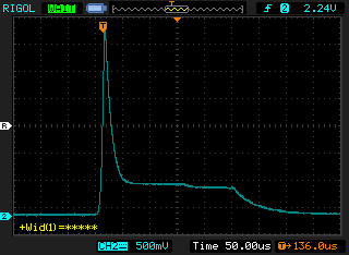
The pulse from a xenon flash
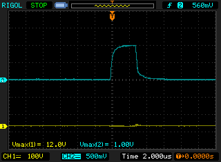
The pulse from an LED flash
Flash speed testing on a budget
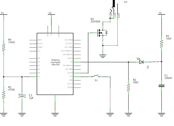
A photodetector will set you back $100 and upwards, and an oscilloscope is hundreds more. If you don’t have these already, this is much too expensive for most people if they just want to check their own flashes and compare them to others. I decided to build a budget version, based around an Arduino. For the actual detector, a photodiode is much more sensitive, accurate and responsive than a photoresistor, so that’s what we’ll use. The photodiode used in the Thorlabs photodetector costs around $30, but that’s overkill for us. I used an Osram SFH 203 photodiode, which cost about 50c. Make sure you get one that’s sensitive to visible light rather than IR. It’s easy to tell the difference: the IR ones are in black (or rather infrared) packages, while the visible ones are clear. We’re operating the photodiode in photoconductive mode by applying a reverse bias. The current measured through it indicates the brightness of the light shining on the diode. We add an RC filter to avoid high frequency noise interfering with our readings. A 50 ohm load resistor gives us a voltage to measure with the Arduino.
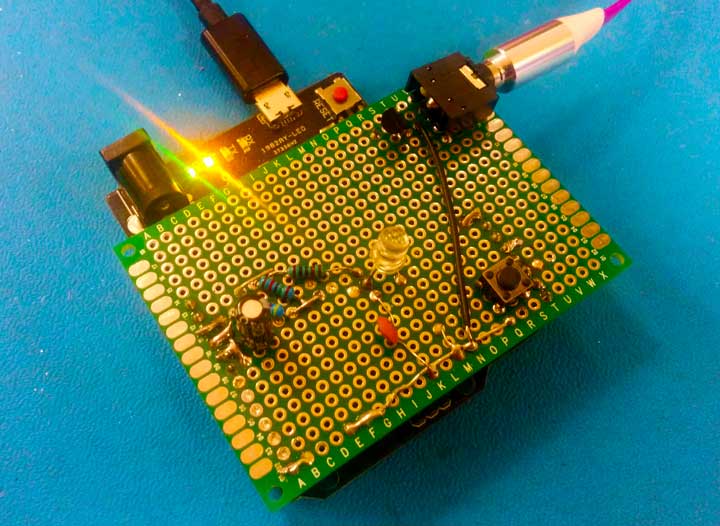
We’ll be building this as an Arduino shield. You can use a protoshield, but I just used a small PCB with some pin headers. If we want to measure lag we also need to trigger the flash so we can measure the time between trigger and flash. I’ve added a 3.5mm audio socket for this. Some flashes (including the Vela One) have 3.5mm trigger sockets, so for those a simple audio cable is enough. For other ones you’ll need a hotshoe or PC sync adapter of some kind. A push button does the triggering. To get a reading for just the pulse width you simply point the flash at the detector and fire it. It will print the pulse width over serial. If you want to measure the lag as well then you need to connect the flash to the shield, point it at the detector, then press the button on the shield. You’ll then get both values over serial.
Wiring it up
As explained above, we’ll be detecting the flash by measuring the voltage from the photodiode. Arduino programmers are probably thinking that I’m about to break out analogRead. Unfortunately that’s far, far too slow. We not only need fast readings but we also need accurate timers and the standard Arduino ones aren’t good enough either. We’ll need to drop down to native AVR code. I’m developing this on a Leonardo, which uses an ATMega32u4 micro. I’m going to be working directly with the micro’s registers, so the code is specific to the Leonardo. With a bit of fiddling it should work on other Arduinos too, but it won’t out of the box.
ATMega chips have a built-in analog comparator which is great for this. This measures whether the voltage on one pin is higher or lower than the reference voltage and generates an interrupt or sets a register accordingly. The reference voltage can either be the micro’s internal reference voltage, or a voltage on an external pin. We’ll be using the latter so that we can set our threshold. Once the voltage from the photodiode goes over that threshold it will trigger an interrupt. A little trial and error with the oscilloscope showed that 100-200mV was a good threshold, so I used a voltage divider to generate this. The Arduino site has a useful page showing pin mappings for the Leonardo. From this I can see AIN0, the analog comparator input pin, is mapped to Arduino digital pin 7. The 32u4 uses the ADC multiplexer for the reference voltage, so we’ll use ADC0, which is Analog Input 5 in Arduino world. We’ll put the push button on an interrupt pin, in this case INT0 which is Digital 3. We’ll trigger the flash via a MOSFET on digital pin 4.
Overview
The sequence is as follows: the user presses the button, triggering the external interrupt. In the interrupt handler we turn on the flash trigger pin and record the current time from timer1, then start timer4. Timer4 overflows after 40µs, at which point we turn off the flash trigger pin. Separately, the analog comparator is constantly watching for a pulse from the photodiode. This will only be triggered by a flash, as anything else will not be bright enough. When it detects a pulse, it stores the current time in the input capture register and triggers the input capture interrupt. Inside the input capture handler we store the pulse start time, reset the timer and flip the comparator to trigger on fall rather than rise. Once the flash ends, the falling edge of the pulse triggers the interrupt again and stores the time in the input capture register. In that handler we set a flag saying a flash has just finished and flip the interrupt again to watch for new flashes. Inside the main loop we see that a flash flag has been set and grab the value from the input capture register. That value is the number of clock cycles between the rising edge and the falling edge: i.e. the pulse width. If the trigger time has been set then it means the flash was triggered by us, and we can calculate the lag too. We convert these values to microseconds and print them over serial.
The code
As I said before, I’m having to use native AVR code as we need access to the faster timers and interrupts, but this can be mixed in with regular Arduino code. If you’re not familiar with AVR registers this can look a little strange but I’ve tried to comment it thoroughly. Most of the weird-looking stuff is setting bits on registers, which is how you configure a microcontroller. The values are all found in the processor’s datasheet. I’ve spent many an hour reading AVR datasheets, and they’re a goldmine of useful information for any Arduino programmer, and vital if you start working directly with the processor.
We’re using two timers. One is for the timing of the pulse width and the lag: i.e. the important stuff. We’re using another timer for things like sending the trigger signal to the flash, debouncing, reset delays and various other housekeeping. First we’ll set up the analog comparator. We’ll use input capture, as that gets us the value of the timer at the exact point that the voltage crossed the threshold. We’ll set these all up in the Arduino setup function.
void setup() {

    //Disable interrupts while we're fiddling with settings.
    cli();

    //Timer4 is our flash trigger pulse and housekeeping timer.
    //Enable overflow and output compare interrupts. Start turned off.
    TIMSK4 = _BV(TOIE4);
    TCCR4A = 0;
    TCCR4B = 0;
    OCR4A  = 1;
}
That’s not so interesting, so let’s get onto the analog comparator. We’re using Timer1, which is normally used by the Arduino Servo library. We’re not using a servo here, so we’re fine. We’ll need to reconfigure it for our needs.
    //Mode 0: normal mode, no port outputs.
    TCCR1A = 0;

    //This sets the clock to no prescale (16MHz).
    //Trigger on rising edge.

    TCCR1B = _BV(CS10) | _BV(ICES1);

    //Enable analog comparator input capture.
    ACSR = _BV(ACIC);

    //Clear input capture interrupt flag - thanks Don
    TIFR1 = _BV(ICF1);

    //Enable input capture interrupts
    TIMSK1  |= _BV(ICIE1);

    //Use multiplexer for our reference voltage.
    //Defaults to ADC0, i.e. PF0/Analog 5
    ADCSRB |= _BV(ACME);

    //Turn off the ADC as we'll be using its multiplexer.
    ADCSRA &= ~_BV(ADEN);

    //Turn off digital input on the comparator negative input (PE6)
    DIDR1 |= _BV(AIN0D);
What we did there is set up Timer1 to run at 16MHz. When the voltage on the analog comparator pin rises above the threshold, the current timer value is stored in a register and an interrupt handler is called. Let’s write that handler.
The 32u4 lets you choose whether to trigger the handler on rise or fall, but annoyingly not both. We need to detect both edges of the pulse so we can check how long it is, so we need a workaround. What this means is that we need to first trigger on rise, and then in that interrupt handler switch to triggering on fall so that we capture the end of the pulse.
// Input capture interrupt
ISR(TIMER1_CAPT_vect) {

    if(bit_is_set(TCCR1B, ICES1)) {
        //We're currently triggering on rise. Change to fall
        TCCR1B &= ~_BV(ICES1);
        //Reset counter
        TCNT1 -= ICR1;
        flashStart = ICR1;
    } else {
        //We're triggering on fall. Change to rise.
        TCCR1B |= _BV(ICES1);
        flash = 1;
    }

}
When we’re triggered by a rising edge (signifying the start of a flash pulse) we set the flashStart value which records the time the pulse started. This is used to measure lag. We reset the timer’s counter when the pulse starts so that we can just read the value in the fall handler to get the length of the pulse. In the fall handler we simply set a flag which we read in the loop. This is because it’s a bad idea to do too much inside an interrupt handler and we certainly shouldn’t be doing any serial comms.
I’ve omitted the setup for the push button pin, but we just set it to input with interrupts on fall and enabled the internal pullup resistor. Here’s the handler.
// Start button pressed
ISR(INT0_vect) {

    if(ignore == 1) {
        return;
    }

    ignore = 1;
    digitalWrite(FLASH_PIN, HIGH);
    triggerTime = TCNT1;
    //Reset and start timer4 with no prescaler
    TCNT4 = 0;
    TCCR4B = _BV(CS40);
    triggering = 1;
}
First thing we do is check “ignore”, which is a debouncing flag. If we pass, then we trigger the flash and record the current time. We start timer4, which will stop the trigger signal when it first overflows which will be after 40 microseconds. This is a long enough pulse to trigger the flash. Here’s the handler that’s triggered by the timer every time it overflows.
// Timer overflow
ISR(TIMER4_OVF_vect) {
    if(triggering == 1) {
        //Turn off the trigger pulse after 1 overflow (~40us)
        digitalWrite(FLASH_PIN, LOW);
    } else if(triggering == 100) {
        //Reset everything after 100 overflows (~4ms)
        //Turn off timer4
        TCCR4B = 0;
        ignore = 0;
        triggerTime = 0;
    }
    triggering++;
}
We use a counter to see how many times we’ve overflowed. On the first overflow we turn off the flash. After 100 overflows (about 4ms) we turn off the timer and start listening for button presses again. We clear the triggerTime value, as after 4ms we can be confident that any flashes were not triggered by the button.
The loop is just used when we’ve got to the end of the flash and are ready to send the results over the serial connection.
void loop() {

    if(flash == 1) {
        //We were triggered by the button
        if(triggerTime > 0) {
            Serial.print("Lag ");
            Serial.print(clockCyclesToMicroseconds(flashStart - triggerTime), DEC);
            Serial.println("us");
        }


        Serial.print("Pulse width ");
        Serial.print(clockCyclesToMicroseconds(ICR1), DEC);
        Serial.println("us");

        Serial.println("********");

        ignore = 0;
        flash = 0;
    }
}
Drawbacks
We’re a little restricted by the fact that the analog comparator on the 32u4 won’t trigger input capture on both edges. Our workaround of flipping the edge that triggers input capture so that we can catch both edges works fine down to around 3µs. Once we’re dealing with pulses shorter that we seem to miss the falling edge. The pulse ends before we can tell the comparator to capture it. There are a few ways we might be able to fix this. One would be to use our own external comparator. We could then wire that up to two input capture pins, one each to capture on rise and fall. This should let us catch both edges. Alternatively, we could improve the firmware to toggle the triggering edge sooner, possibly by using naked interrupts.
Results
So, what about the results? I have tested this with three flashes, and compared the results to those from the oscilloscope. I have two speedlights that I used in these tests, as well as the Vela One high speed flash.
| Flash | Setting | Lag (µs) | Pulse width (µs) |
|---|---|---|---|
| Yongnuo YN560-II | 1/128 | 60-62 | 146-158 |
| Olympus FL-600R | 1/128 | 77-79 | 128-150 |
| Vela One | 3µs* | 8 | 3 |
* This is not the Vela One’s fastest setting, but the tester can’t handle pulses shorter than this. The real shortest pulse is 500ns
If you try building this please share your results. I’d be particularly interested if you have an airgap flash to test (though you may hit the speed limit described above). The code is on Github. If you have any suggestions for improving the code or the design, please do submit a pull request or leave a comment.
I wrote this post four years ago, when I was developing the Vela One. It’s now available, and is still the fastest flash on the market.